RESISTOR:
![]() Resistor is energy absorbing element in electrical circuit. It's unit is ohm.
Resistor is energy absorbing element in electrical circuit. It's unit is ohm.
The potential difference v across the terminals of resistor R, is directly proportional to the current i flowing through it.
That is,
V=IR; Here R is called the resistance of resistor R
The reciprocal of resistance is defined as conductance( G).
Hence,
(1/R)=G & I=VG
The power absorbed by a resistor is given by
P=VI
INDUCTOR:
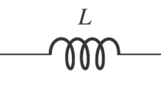 Inductor is an energy storing element in electrical circuit. It's unit is henry.
The potential difference v across the terminals of inductor is directly proportional to rate of change of current through it.
That is, [tex]V = L\frac{{di}}{{dt}}[/tex]; Here the term L is the proportionality constant and known as inductance of the inductor.
Hence, current through inductor is
[tex]I = \frac{1}{L}\int\limits_0^t {} Vdt + I(0)[/tex]
Where I(0) is the initial current of the inductor.
The energy stored in an inductor over the interval [tex]\left( {{t_1},{t_2}} \right)[/tex] is,
[tex]E\left( {{t_1},{t_2}} \right) = \int\limits_{{t_1}}^{{t_2}} {VIdt = \int\limits_{{t_1}}^{{t_2}} {L(dI/dt)} } Idt = \frac{L}{2}[\mathop I\nolimits^2 ({t_2})\_\mathop I\nolimits^2 ({t_1})][/tex]
Inductor store the energy in the form of current.
CAPACITOR:
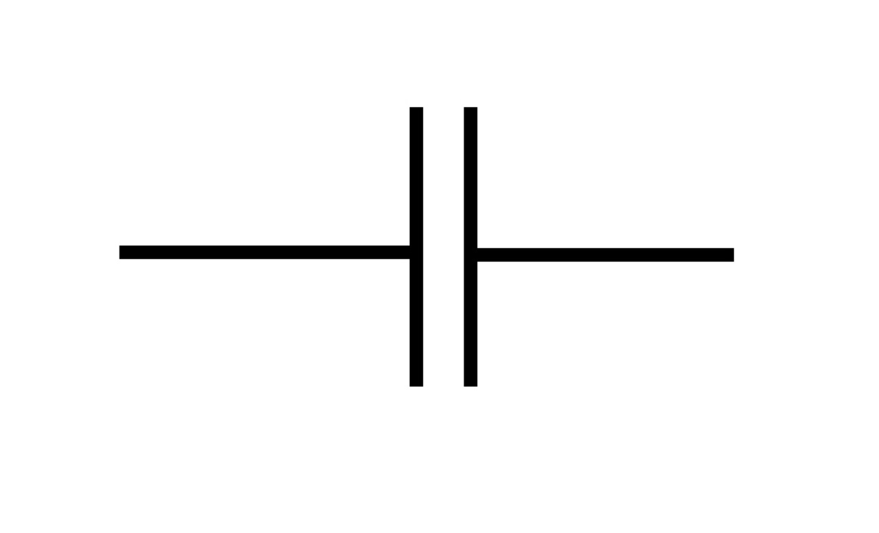 Capacitor is another energy storing element in electrical circuit. It's unit is farad.
The potential difference v between the terminals of capacitor is proportional to the charge q on it. That is
[tex]v \propto q[/tex]
v=q/C; where C is the proportionality constant and is called the capacitance.
Now, [tex]i = \frac{{dq}}{{dt}} = C(\frac{{dv}}{{dt}})[/tex]
[tex]\int {dv = \frac{1}{C}\int {idt} } [/tex]
Hence, [tex]V(t) = \frac{1}{C}\int\limits_0^t {i(t)dt} + q(0)/C[/tex]
where q(0) is the initial charge across the capacitor C.
The energy stored in a capacitor over the interval [tex]\left( {{t_1},{t_2}} \right)[/tex] is,
[tex]E\left( {{t_1},{t_2}} \right) = \int\limits_{{t_1}}^{{t_2}} {VIdt = \int\limits_{{t_1}}^{{t_2}} {VC(dv/dt)} } dt = \frac{C}{2}[\mathop V\nolimits^2 ({t_2})\_\mathop V\nolimits^2 ({t_1})][/tex]
Capacitor store the energy in the form of voltage.