A magnetic coupling is a coupling where energy can be transferred from one circuit to another, not connected through any physical mechanical connection but using magnetic flux linking both circuits.The two circuits are then said to be magnetically coupled.Mutual inductance results through the presence of a common magnetic flux which links two coils and maybe defined in terms of this common magnetic flux.
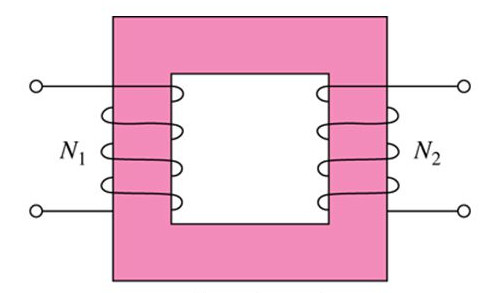
Transformer working is a common example of mutual inductance.
The basis of this magnetic action is Faraday's law electromagnetic induction, which states that an electromotive force is induced in a closed circuit when the magnetic flux linking with the circuit is changed. And by Lenz's law it can be said that, the induced electromotive force is always in such a direction as to oppose the flux change, and its magnitude is numerically equal to the rate of change of flux linkage.
To understand magnetic coupling we need to know about,
- Coupled inductor
- Self inductance
- mutual inductance
COUPLED INDUCTOR:
When the magnetic flux produced by an inductor links another inductor, these inductors are said to be coupled and there exists a mutual inductance that relates the current in one inductor to the flux linage in the other inductor. The amount of mutual inductance between the two windings determines the shape of the frequency response curve.
SELF INDUCTANCE:
A coil of N turns carrying current I in the clockwise direction shown. The current is steady so the magnetic flux through the loop remain constant.
However, suppose the current I changes with time then according to Faraday's Law an induced emf will arise to oppose the change.
The induced current will flow clockwise, if [tex]\frac{{dI}}{{dt}} < 0[/tex]
and counterclockwise if [tex]\frac{{dI}}{{dt}} > 0[/tex].
The property of the loop in which its own magnetic field opposes any change in current is called self-inductance and the emf generated is called self-induced emf or back emf([tex]{\varepsilon _L}[/tex]).
Mathematically [tex]{\varepsilon _L}[/tex] can be written as,
[tex]{\varepsilon _L} = - N\frac{{d{\Phi _B}}}{{dt}}[/tex]
and is related to self-inductance L by,
[tex]{\varepsilon _L} = - L\frac{{dI}}{{dt}}[/tex]
Therefore, [tex]L = N\frac{{{\Phi _B}}}{I}[/tex]
MUTUAL INDUCTANCE:
When two coils placed very close to each other, the magnetic flux caused by current in one coil links with other coil and induces some voltage in the second coil. This phenomena is known as mutual inductance.
 Consider two coils placed closed each other as shown,
Coil 1 has [tex]{N_1}[/tex] turns and carries [tex]{{I_1}}[/tex] which is cause of magnetic field [tex]{B_1}[/tex].
Coil 2 placed closed to coil 1, some of magnetic field lines through coil 1 also pass through coil 2.
Time rate of change of magnetic flux [tex]{{\Phi _{21}}}[/tex] in coil 2 is proportional to the time rate of change of the current in coil 1 and thus the voltage can be written as,
[tex]{\varepsilon _{21}} = {N_2}\frac{{d{\Phi _{21}}}}{{dt}} = {N_2}\frac{{d{\Phi _{21}}}}{{d{I_1}}} \times \frac{{d{I_1}}}{{dt}} = {M_{21}}\frac{{d{I_1}}}{{dt}}[/tex]
Where,[tex]{M_{21}} = {N_2}\frac{{{\Phi _{21}}}}{{{I_1}}}[/tex] is called the mutual inductance of coil 2 with respect to coil1.
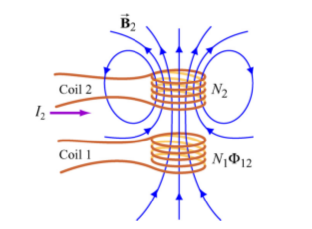 Similarly suppose coil 2 has [tex]{N_2}[/tex] turns and carries [tex]{{I_2}}[/tex] which is cause of magnetic field [tex]{B_2}[/tex] and [tex]{{I_2}}[/tex] is varying with time. The induced emf in coil1 becomes,
[tex]{\varepsilon _{12}} = {N_1}\frac{{d{\Phi _{12}}}}{{dt}} = {N_1}\frac{{d{\Phi _{12}}}}{{d{I_2}}} \times \frac{{d{I_2}}}{{dt}} = {M_{12}} \times \frac{{d{I_2}}}{{dt}}[/tex]
where, [tex]{M_{12}} = {N_1}\frac{{{\Phi _{12}}}}{{{I_2}}}[/tex] is mutual inductance of coil1 with respect to coil2.
Using the reciprocity theorem which combines Ampere's law and the Biot-Savart law, it can be shown that the mutual inductances are,
[tex]{M_{12}} \equiv {M_{21}} \equiv M[/tex]
COEFFICIENT OF COUPLING:
Coefficient of coupling between two coupled coil is defined as the ratio of the flux linking to the other coil to the total flux.
i.e. [tex]k = \frac{{{\phi _{21}}}}{{{\phi _1}}} = \frac{{{\phi _{12}}}}{{{\phi _2}}}[/tex]
where,[tex]{{\phi _{12}}}[/tex]is flux of coil 1 through coil 2
[tex]{{\phi _{21}}}[/tex]is flux of coil 2 through coil 1
k attains a maximum value of unity.
Now the mutual inductance between two coils is,
[tex]M = \frac{{{N_2}{\phi _{21}}}}{{{I_1}}} = \frac{{{N_1}{\phi _{12}}}}{{{I_2}}}[/tex]
\[\begin{array}{l}
{M^2} = \frac{{{N_2}{\phi _{21}}}}{{{I_1}}} \times \frac{{{N_1}{\phi _{12}}}}{{{I_2}}} = \frac{{{N_2}k{\phi _2}}}{{{I_1}}} \times \frac{{{N_1}k{\phi _1}}}{{{I_2}}}\\
= {k^2}\left( {\frac{{{N_2}{\phi _2}}}{{{I_1}}}} \right) \times \left( {\frac{{{N_1}{\phi _1}}}{{{I_2}}}} \right) = {k^2}{L_1}{L_2}
\end{array}\]
where, [tex]{L_1}[/tex] and [tex]{L_2}[/tex] are the self inductance of the coils.
Therefore, [tex]k = \frac{M}{{\sqrt {{L_1}{L_2}} }}[/tex]
- 1290 views