1.4.5 PWM Rectifier
The most interesting reduction technique of current harmonic is a PWM (active) rectifier (Fig. 1.3).

Two types of PWM converters, with a voltage source output (Fig. 1.4) and a current source output (Fig. 1.5) can be used.
First of them (fig-1.4) called a boost rectifier (increases the voltage) works with fixed DC voltage polarity.
And the second (fig-1.5), called a buck rectifier (reduces the voltage) operates with fixed DC current flow.

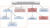
Fig-1.4: PWM boost rectifier

Fig-1.5 PWM buck rectifier
Among the main features of PWM rectifiers are:
-
bi-directional power flow,
-
nearly sinusoidal input current,
-
regulation of input power factor to unity, or leading.
-
Low harmonic distortion of line current (THD below 5%),
-
adjustment and stabilization of DC-link voltage (or current),
-
Reduced capacitor (or inductor) size due to the continuous current.
Furthermore, it can be properly operated under line voltage distortion and notching, and line voltage frequency variations. Similar to the PWM active filter, the PWM rectifier has a complex control structure; the efficiency is lower than the diode rectifier due to extra switching losses. A properly designed low-pass passive filter is needed in front of the PWM rectifier due to EMI concerns. But this technique is most impressive to advances in power semiconductor devices (enhanced speed and performance, and high ratings) and digital signal processes, which allow fast operation and cost reduction.
By using proper switching sequences and controlling the switching signal “unity power factor control” can be achieved with PWM rectifier Technology.
- 117 views