1.4.4 Active PWM filter
An alternative to the passive filter is use of the active PWM filter (AF), which displays better dynamics and controls the harmonic and fundamental currents. Active filters are mainly divided into two different types: the active shunt filter (current filtering) (Fig.1.2) and the active series filter (voltage filtering).
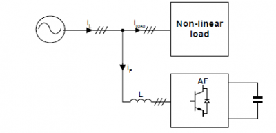
Fig-1.2: Active PWM shunt filter
The three-phase two-level shunt AF consists of six active switches and its topology is identical to the PWM inverter. AF represents a controlled current source ![]() which when added to the load current
which when added to the load current ![]() yields sinusoidal line current
yields sinusoidal line current ![]() .
.
Active Filter provide:
-
compensation of fundamental reactive components of load current,
-
load symetrization (from grid point of view),
-
harmonic compensation much better than in passive filters.
In spite of the excellent performance, AFs possess certain disadvantages as complex control, switching losses and EMC problems (switching noise is present in the line current and even in the line voltage). Therefore, for reduction of these effects, inclusion of a small low-pass passive filter between the line and the AF is necessary.
- 25 views