


It is easy to calculate the steady current, which flows in a circuit, when it is connected to a d.c. generator or battery and also when circuit connected to an alternator or ac source. These currents are known as steady currents because in such cases it is assumed that,
- The circuit components are constant
- The circuit has been connected to the generator long enough for any disturbance produced on initial switching, to resolve itself.
In general transients response occur in a circuit whenever,
- An apparatus or circuit suddenly connected to or disconnected from the supply
- A circuit is shorted
- There is sudden change in the applied voltage from one finite value to another.
The time response of a system consist of two parts
- a final steady state or normal current
- a transient current superimposed on the steady state current
The transient currents are not driven by any part of applied voltage but are entirely associated with the changes in the stored energy in inductors and capacitor. Since there is no stored energy in resistors, there are no transients in pure resistive circuits.
Discharging and Charging of inductor: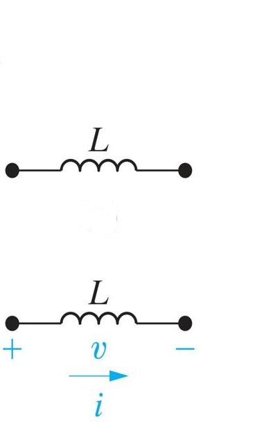
In the figure the circuit symbol of inductor is shown. The voltage across inductor can be written as,
[tex]v = L\frac{{di}}{{dt}}[/tex]
Hence, current across inductor,
[tex]\begin{array}{l}
i = \frac{1}{L}\int\limits_{ - \infty }^t {vdt} = \frac{1}{L}\int\limits_{ - \infty }^0 {vdt} + \frac{1}{L}\int\limits_0^t {vdt} \\
= i({0^ - }) + \frac{1}{L}\int\limits_0^t {vdt}
\end{array}[/tex]
where,[tex]i({0^ - })[/tex] is initial current of the inductor.
The energy stored in an inductor over the interval [tex]\left( {{t_1},{t_2}} \right)[/tex] is,
[tex]E\left( {{t_1},{t_2}} \right) = \int\limits_{{t_1}}^{{t_2}} {vidt = \int\limits_{{t_1}}^{{t_2}} {L(di/dt)} } idt = \frac{L}{2}[\mathop i\nolimits^2 ({t_2})\_\mathop i\nolimits^2 ({t_1})][/tex]
Inductor store the energy in the form of current.
At discharging, E(t) decreases and [tex]E(\infty ) = 0[/tex]
current i decreases and[tex]i(\infty ) = 0[/tex]
therefore,
[tex]\begin{array}{l} \frac{{di}}{{dt}} = - ve\\ v = L\frac{{di}}{{dt}} = - ve \end{array}[/tex]
when inductor will discharge its voltage will be negative.
at steady state,[tex]v(\infty ) = L\frac{{di(\infty )}}{{dt}} = 0[/tex]
Hence at steady state inductor will act as short circuited.
At charging, E(t) increases and [tex]E(\infty ) = maximum[/tex]
current i increases and[tex]i(\infty ) = maximum[/tex]
therefore,
[tex]\begin{array}{l} \frac{{di}}{{dt}} = + ve\\ v = L\frac{{di}}{{dt}} = + ve \end{array} [/tex]
when inductor will charge its voltage will be positive.
at steady state,[tex]v(\infty ) = L\frac{{di(\infty )}}{{dt}} = 0[/tex]; (Because derivation of any number always be zero).
Hence at steady state inductor will act as short circuited.
Inductor opposes the sudden change in current in it.
Discharging and Charging of capacitor:
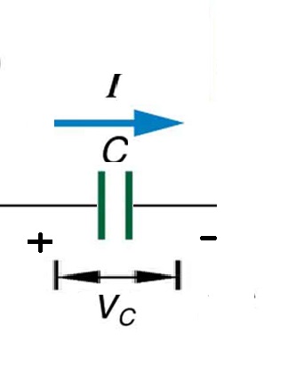 In the figure the circuit symbol of capacitor is shown. The current across capacitor can be written as,
[tex]I = C\frac{{d{V_c}}}{{dt}}[/tex]
Hence voltage across capacitor,
[tex]{V_c} = \frac{1}{C}\int\limits_{ - \infty }^t {Idt} = \frac{1}{C}\int\limits_{ - \infty }^0 {Idt} + \frac{1}{C}\int\limits_0^t {Idt} [/tex]
where,[tex]\frac{1}{C}\int\limits_{ - \infty }^0 {Idt} = {V_c}({0^ - })[/tex] is the initial voltage of the capacitor.
The energy stored in a capacitor over the interval [tex]\left( {{t_1},{t_2}} \right)[/tex] is,
[tex]E\left( {{t_1},{t_2}} \right) = \int\limits_{{t_1}}^{{t_2}} {{V_c}Idt = \int\limits_{{t_1}}^{{t_2}} {{V_c}C(dv/dt)} } dt = \frac{C}{2}[\mathop {V_c}\nolimits^2 ({t_2})\_\mathop {V_c}\nolimits^2 ({t_1})][/tex]
Capacitor store the energy in the form of voltage.
At discharging, E(t) decreases and [tex]E(\infty ) = 0[/tex]
voltage [tex]{V_c}[/tex] decreases and[tex]{V_c}(\infty ) = 0[/tex]
therefore,
[tex] \begin{array}{l} \frac{{d{V_c}}}{{dt}} = - ve\\ I = C\frac{{d{V_c}}}{{dt}} = - ve \end{array} [/tex]
when capacitor will discharge its current will be negative.
at steady state,[tex]I(\infty ) = C\frac{{d{V_c}(\infty )}}{{dt}} = 0[/tex]
Hence at steady state capacitor will act as open circuited.
At charging, E(t) increases and [tex]E(\infty ) = maximum[/tex]
voltage [tex]{V_c}[/tex] increases and[tex]{V_c}(\infty ) = maximum[/tex]
therefore,
[tex] \begin{array}{l} \frac{{d{V_c}}}{{dt}} = + ve\\ I = C\frac{{d{V_c}}}{{dt}} = + ve \end{array} [/tex]
when capacitor will charge its current will be positive.
at steady state,[tex]I(\infty ) = C\frac{{d{V_c}(\infty )}}{{dt}} = 0[/tex]; (Because derivation of any number always be zero).
Hence at steady state capacitor will act as open circuited.
Capacitor opposes sudden changes of voltage in it.
- 141 views