


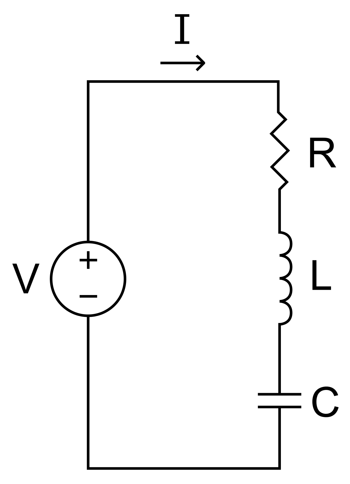
 The basic series resonant circuit is shown in figure. A sinusoidal voltage V sends a current I through the circuit.The circuit is said to be resonant when the resultant reactance of circuit is zero. The impedance of circuit at any frequency [tex]\omega [/tex] is
[tex]Z = R + j\left( {\omega L - \frac{1}{{\omega C}}} \right)[/tex]
The the current,
[tex]I = \frac{V}{{R + j\left( {\omega L - \frac{1}{{\omega C}}} \right)}}[/tex]
The phase angle of current is given by,
[tex]\phi = - {\tan ^{ - 1}}\frac{{\omega L - \frac{1}{{\omega C}}}}{R}[/tex]
At resonance, the circuit must have unity power factor i.e.
[tex]\left( {\omega L - \frac{1}{{\omega C}}} \right) = 0[/tex]
Hence, [tex]{\omega _0}L = \frac{1}{{{\omega _0}C}}[/tex]
\[\begin{array}{l}
{\omega _0} = \frac{1}{{\sqrt {LC} }}\\
{f_0} = \frac{1}{{2\pi \sqrt {LC} }}
\end{array}\]
where [tex]{f_0}[/tex] is the frequency of resonance in hertz.
At resonance current is,[tex]{I_0} = \frac{V}{R}[/tex]
- As [tex]\omega \to 0;\phi \to {\tan ^{ - 1}}\left( {\frac{1}{{\omega RC}}} \right)[/tex] in this case the current leads the voltage with phase relationship being like that of an RC circuit.
- As [tex]\omega \to \infty ;\phi \to - {\tan ^{ - 1}}\left( {\frac{{\omega L}}{R}} \right)[/tex] in this case current lags the voltage with the phase relationship being like that of RL circuit.
- As [tex]\omega = {\omega _0};\phi = 0[/tex] and in this case the current and the volage are in phase, yhe circuit behaving like purely resistive circuit.
Hence, at any frequency lower than resonant frequency circuit behaves as capacitive circuit. And at any frequency higher than resonant frequency circuit behaves as inductive circuit.
- 255 views