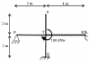
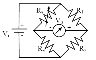
 Q. A strain gauge forms one arm of the bridge shown in the figure below and has a nominal resistance without any load as Rs = 300 ohm . Other bridge resistances are R1 = R2 = R3 = 300 ohm . The maximum permissible current through the strain gauge is 20 mA. During certain measurement when the bridge is excited by maximum permissible voltage and the strain gauge resistance is increased by1% over the nominal value, the output voltage V0 in mV is
Options: (A) 56.02 (B) 40.83 (C) 29.85 (D) 10.02
Ans: C