


Transformers
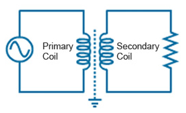 The basic principle of the transformer is mutual inductance between two circuit linked by a common magnetic field. When an electric circuit carrying a current, then a magnetic field created around the current carrying conductor. If the current in the circuit is alternating then the magnetic field at any point in the surrounding medium will change in magnitude and direction in accordance with the changes of current with time.
Standard Parameter of a Transformer
- Input Voltage
- Output Voltage
- Phase
- Frequency
- Winding Material
- Temperature Rise
- Insulation Class
- Max Impedance
- Minimum Efficiency
- Regulation
- Audible Noise
- Electrostatic Shield
- Taps
- Enclosure
- Applicable Standards
[tex]\Phi = {\Phi _m}\sin \omega t[/tex] ------------ (1)
[tex]\begin{array}{l}
e = - \frac{d}{{dt}}(\Phi T)\\
= - T\frac{{d\Phi }}{{dt}}\\
= - T\frac{d}{{dt}}({\Phi _m}\sin \omega t)\\
= - T\omega {\Phi _m}\cos \omega t\\
= T\omega {\Phi _m}sin(\omega t - \frac{\pi }{2})\\
= {E_m}sin(\omega t - \frac{\pi }{2})
\end{array}[/tex]
$$\begin{array}{l}
{E_m} = T\omega {\Phi _m}\\
{E_{rms}} = E = \frac{{E{}_m}}{{\sqrt 2 }}\\
E = \frac{{T\omega {\Phi _m}}}{{\sqrt 2 }} = \frac{{T2\pi f{\Phi _m}}}{{\sqrt 2 }}
\end{array}$$
[tex]E = 4.44{\Phi _m}fT[/tex] ------------ (2)
[tex]\frac{{{E_1}}}{{{E_2}}} = \frac{{{T_1}}}{{{T_2}}}[/tex] ------------ (3)
[tex]e = - \frac{d}{{dt}}(\Phi T)[/tex] ------------ (4)
[tex][/tex] ------------ (.)